4.9 KiB
4.9 KiB
Pin Configuration
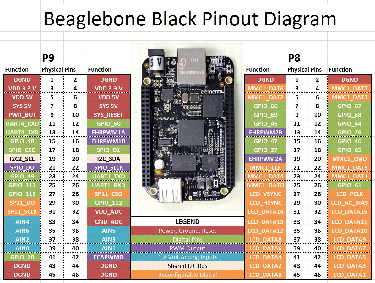
The following pins on the Beaglebone Black's P9 and P8 headers must be connected. See the section on the Linux Device Tree Overlay for details on the pinmux. In most cases, the SPI0 and LCD_DATA[15:0] bus follow the default (MODE0) pinmux. The 24-bit configuration is slightly different, and requires different muxing of some pins that are normally GPIO.
P8 Header
| Power and Data | |||
|---|---|---|---|
| Ground | ₁ ■ | □ ₂ | |
| +3.3v | ₃ ■ | □ ₄ | |
| ₅ □ | □ ₆ | ||
| ₇ □ | □ ₈ | ||
| ₉ □ | □ ₁₀ | ||
| ₁₁ □ | ■ ₁₂ | Reset | |
| ₁₃ □ | □ ₁₄ | ||
| ₁₅ □ | □ ₁₆ | ||
| Chip Select | ₁₇ ■ | ■ ₁₈ | SPI Data |
| ₁₉ □ | □ ₂₀ | ||
| ₂₁ □ | ■ ₂₂ | SPI Clock | |
| ₂₃ □ | □ ₂₄ | ||
| ₂₅ □ | □ ₂₆ | ||
| ₂₇ □ | □ ₂₈ | ||
| ₂₉ □ | □ ₃₀ | ||
| ₃₁ □ | □ ₃₂ | ||
| ₃₃ □ | □ ₃₄ | ||
| ₃₅ □ | □ ₃₆ | ||
| ₃₇ □ | □ ₃₈ | ||
| ₃₉ □ | □ ₄₀ | ||
| ₄₁ □ | □ ₄₂ | ||
| ₄₃ □ | □ ₄₄ | ||
| ₄₅ □ | □ ₄₆ |
P9 Header
| 16-Bit | 24-Bit | |||||||
|---|---|---|---|---|---|---|---|---|
| 📕R[ 0 ] | ₁ ■ | ■ ₂ | 📘B[ 0 ] | ₁ □ | □ ₂ | |||
| ₃ □ | □ ₄ | ₃ □ | □ ₄ | |||||
| ₅ □ | □ ₆ | ₅ □ | □ ₆ | |||||
| ₇ □ | □ ₈ | ₇ □ | □ ₈ | |||||
| ₉ □ | □ ₁₀ | ₉ □ | □ ₁₀ | |||||
| ₁₃ □ | □ ₁₄ | Active, unused | ₁₃ ■ | ■ ₁₄ | Active, unused | |||
| ₁₁ □ | □ ₁₂ | Active, unused | ₁₁ ■ | ■ ₁₂ | Active, unused | |||
| ₁₅ □ | □ ₁₆ | 📕R[ 0 ] | ₁₅ ■ | ■ ₁₆ | 📘B[ 0 ] | |||
| ₁₇ □ | □ ₁₈ | Active, unused | ₁₇ ■ | ■ ₁₈ | Active, unused | |||
| ₁₉ □ | □ ₂₀ | Active, unused | ₁₉ ■ | ■ ₂₀ | Active, unused | |||
| ₂₁ □ | □ ₂₂ | ₂₁ □ | □ ₂₂ | |||||
| ₂₃ □ | □ ₂₄ | ₂₃ □ | □ ₂₄ | |||||
| ₂₅ □ | □ ₂₆ | ₂₅ □ | □ ₂₆ | |||||
| VSYNC | ₂₇ ■ | ■ ₂₈ | Pixel Clock | VSYNC | ₂₇ ■ | ■ ₂₈ | Pixel Clock | |
| HSYNC | ₂₉ ■ | ■ ₃₀ | Display Enable | HSYNC | ₂₉ ■ | ■ ₃₀ | Display Enable | |
| 📕R[ 4 ] | ₃₁ ■ | ■ ₃₂ | 📕R[ 5 ] | 📘B[ 4 ] | ₃₁ ■ | ■ ₃₂ | 📘B[ 5 ] | |
| 📕R[ 3 ] | ₃₃ ■ | ■ ₃₄ | 📕R[ 1 ] | 📘B[ 3 ] | ₃₃ ■ | ■ ₃₄ | 📘B[ 1 ] | |
| 📕R[ 2 ] | ₃₅ ■ | ■ ₃₆ | 📗G[ 5 ] | 📘B[ 2 ] | ₃₅ ■ | ■ ₃₆ | 📗G[ 5 ] | |
| 📗G[ 3 ] | ₃₇ ■ | ■ ₃₈ | 📗G[ 4 ] | 📗G[ 3 ] | ₃₇ ■ | ■ ₃₈ | 📗G[ 4 ] | |
| 📗G[ 1 ] | ₃₉ ■ | ■ ₄₀ | 📗G[ 2 ] | 📗G[ 1 ] | ₃₉ ■ | ■ ₄₀ | 📗G[ 2 ] | |
| 📘B[ 5 ] | ₄₁ ■ | ■ ₄₂ | 📗G[ 0 ] | 📕R[ 5 ] | ₄₁ ■ | ■ ₄₂ | 📗G[ 0 ] | |
| 📘B[ 3 ] | ₄₃ ■ | ■ ₄₄ | 📘B[ 4 ] | 📕R[ 3 ] | ₄₃ ■ | ■ ₄₄ | 📕R[ 4 ] | |
| 📘B[ 1 ] | ₄₅ ■ | ■ ₄₆ | 📘B[ 2 ] | 📕R[ 1 ] | ₄₅ ■ | ■ ₄₆ | 📕R[ 2 ] |